MIL-DTL-62366D(AT)
1000 lb (454 kg/2 /3 /6
)
Z
DOWN
6 INCH (15 cm)
RADIUS /3
NASM90726-73/1/7 /8
W/FLAT WASHER,
4 PLACES
Y
NASM90726-63/1 /7 /8
W/FLAT WASHER,
3 PLACES
350 lb (160 kg)/2 /3 /6
500 lb (152 kg)/2 /4
ATTACHING
BOLT HOLES
BOTTOM
OF BASE
UP
X
200 lb (61 kg) (UP)5
/
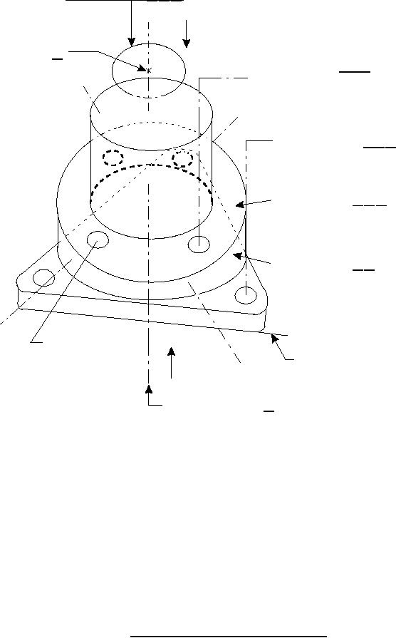
NOTES:
1. Or commercial equivalent.
2. Apply to surface indicated, 2.34 in. (5.94 cm) above base. Load applied via attaching
bolt holes.
3. Combined load case A.
4. Load case B.
5. Load case C.
6. Combined load applied 180 apart.
7. Screw length may be altered provided that suitable engagement of mating nut is
maintained.
8. Torque to 180-190 lbf-in (20 to 21 N-m).
9. The Z axis is designated as vertical.
10. All axes within the x-y plane are designated as horizontal.
FIGURE 1. Coordinate system, slip ring assembly.
7
For Parts Inquires call Parts Hangar, Inc (727) 493-0744
© Copyright 2015 Integrated Publishing, Inc.
A Service Disabled Veteran Owned Small Business