MIL-DTL-46789D(AT)
c. Shaft in a horizontal position.
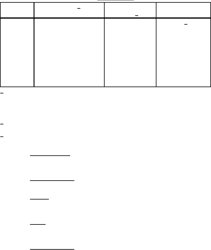
TABLE I. Electrical output.
Resistive loads
Rotor shaft input 1/ torque
Peak output voltage
Condition
(Nm) ±10%
(minimum)
(ohms) 2/
A
7.9
1.47 ±1%
3.1 3/
B
7.9
20.50 ±1%
27.0
C
7.9
Open circuit
44.0
D
11.3
1.47 ±1%
3.8
E
11.3
20.50 ±1%
38.7
F
11.3
Open circuit
60.0
G
14.7
1.47 ±1%
4.4
H
14.7
20.50 ±1%
49.4
I
14.7
Open circuit
74.0
1/ Specified torque is the applied torque at the start of the stroke measured after 5 of shaft
rotation when the backlash of the gear drive mechanism is eliminated. Torque should be
sufficiently constant throughout the stroke so that neither maximum nor minimum values of
torque deviate from average torque by more than 15%. Torque at no point in the power
stroke may exceed the maximum specific value of torque.
2/ Pure resistive load with no more than 1% inductive impedance component at 1000 Hertz
(Hz).
3/ Shall be 0.9 volts minimum 50 milliseconds after peak voltage.
NOTE: Nm = Newton meters, % = percent
3.4.3 Dielectric strength. The assembly shall operate safely at its rated voltage and
withstand momentary overpotentials due to switching, surges, and similar phenomena
(see 4.6.3).
3.4.4 Insulation resistance. The assembly shall have an insulation resistance of not less
than 100 megohms between the internal wiring and the case (see 4.6.4).
3.4.5 Rotation. The direction of rotation of the handle to produce the electrical output
shall be clockwise when viewed from the handle end. One cycle of rotation shall be 150 ±5 and
return to original position (see 4.6.5).
3.4.6 Torque. The assembly shall show no evidence of failure, electrically or
mechanically, after repeated operation at 14.7 N-m of torque throughout the complete rotation of
the rotor shaft (see 4.6.5.1).
3.4.7 Operational stability. The assembly shall withstand 10,000 cycles of operation
without failure (see 4.6.5.1).
5
For Parts Inquires call Parts Hangar, Inc (727) 493-0744
© Copyright 2015 Integrated Publishing, Inc.
A Service Disabled Veteran Owned Small Business